
Fluoride Ion Batteries
The increasing demand for the performance of energy storage systems is driving the search for alternative battery chemistries beyond Lithium ion batteries (LIBs). Na-, Mg-, Al-, Cl-, K- and F-ion batteries have been introduced as alternative electrochemical systems. Rechargeable batteries based on a fluoride anion shuttle are a promising with energy densities of more than 5000 WhL-1 (50% above the theoretical capacity of the Li air cell). The fluoride ion battery, based on a solid-state electrolyte, is currently developed in the group of Prof. Max Fichtner at the KIT. Figure 1 shows a schematic of a fluoride ion battery, illustrating the cycling process. The cell consists of a metal (Mʹ) electrode as anode and a metal fluoride (MFx) electrode as cathode in the charged state. During discharging, fluoride anions (F-) will migrate from the cathode (MFx) to the anode (Mʹ) through the electrolyte forming a metal fluoride MʹFx at the anode. At the same time, the electrons provide the work in the external circuit moving from anode to cathode. The equations of the corresponding cathodic and anodic reactions that describe the discharging process are as follows:
x e-+ MFx → M+ x F- (at cathode)
x F-+ M' → M' Fx+ x e- (at anode)
Understanding the compositional, structural and morphological changes occurring at the electrodes during cycling is essential to improve the performance of fluoride ion batteries. Therefore, TEM has been chosen to study all-solid-state fluoride ion batteries ex situ and in situ.
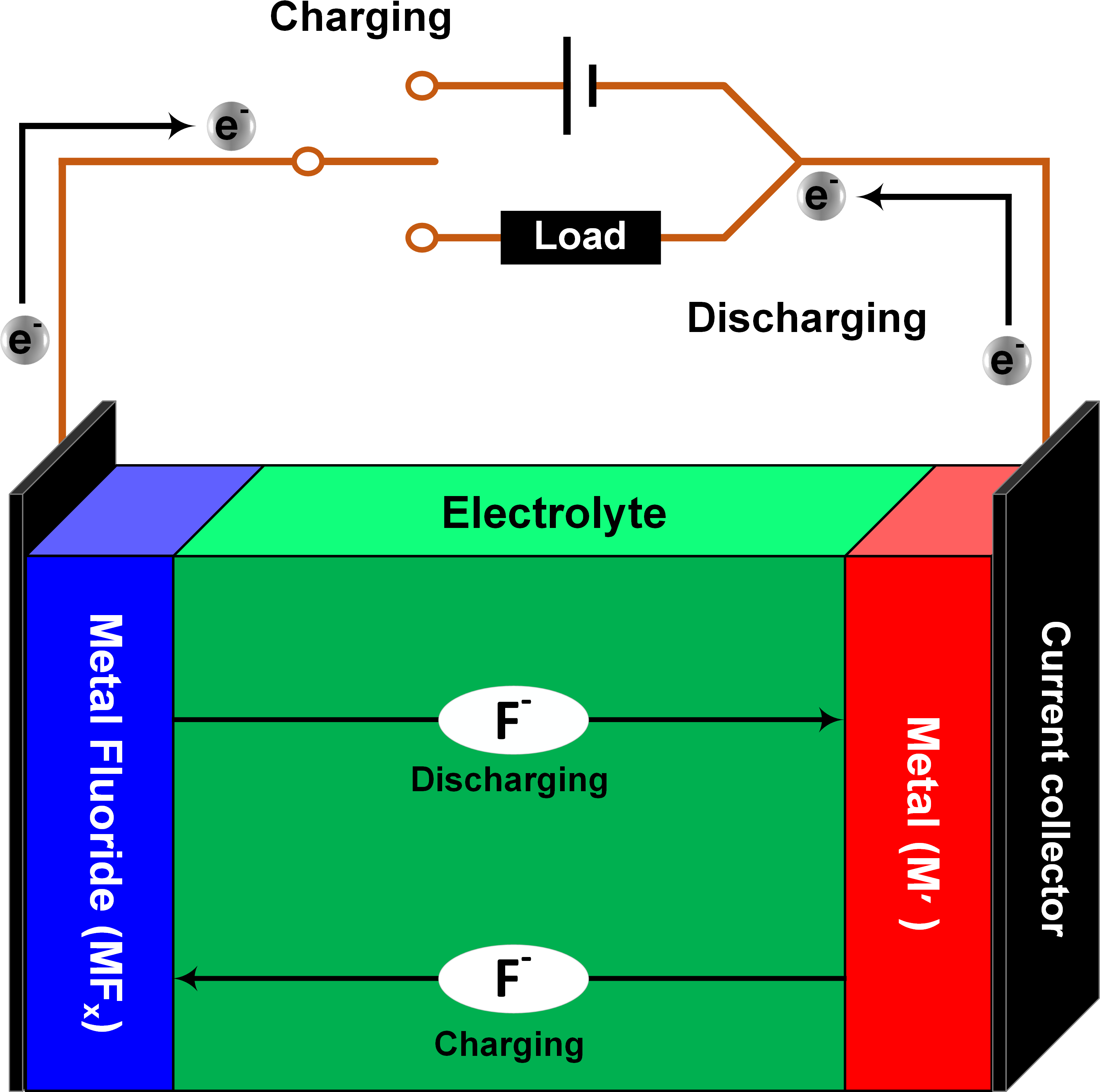
Figure 1: Schematic of Fluoride ion battery
1. Ex situ TEM studies of fuoride ion batteries
In collaboration with the group of Prof. Max Fichtner, interfacial studies were performed by TEM to understand the structural changes at the cathode-electrolyte and anode-electrolyte interfaces, providing new insight into the conversion reaction as well as the degradation mechanism of fluoride ion batteries. The fluoride ion battery consisted of a CuF2 composite as cathode, La0.9Ba0.1F2.9 as an electrolyte, and a La-sheet as anode. The electrochemical cycling was performed at an elevated temperature of 150 ˚C by applying a current density of 10 mA cm-2. Three different states of the system have been studied, as-prepared, discharged, and recharged. Our FIB was used to lift out two lamellae from each pellet at the electrodes-electrolyte interfaces. HRTEM analysis of the cathode confirmed the formation of Cu metal after discharging as a result of CuF2 reduction, while the copper fluoride was formed after recharging, validating the concept of the fluoride ion battery (Figure 2). Moreover, The TEM investigation of the anode-electrolyte interface revealed a structural variation upon cycling with the formation of intermediate layers (Figure 3) consisting of LaF3 and La2O3 after discharging. During recharging LaOF was irreversibly formed providing one explanation for the reduced capacity of the battery after recharging (Figure 3d).
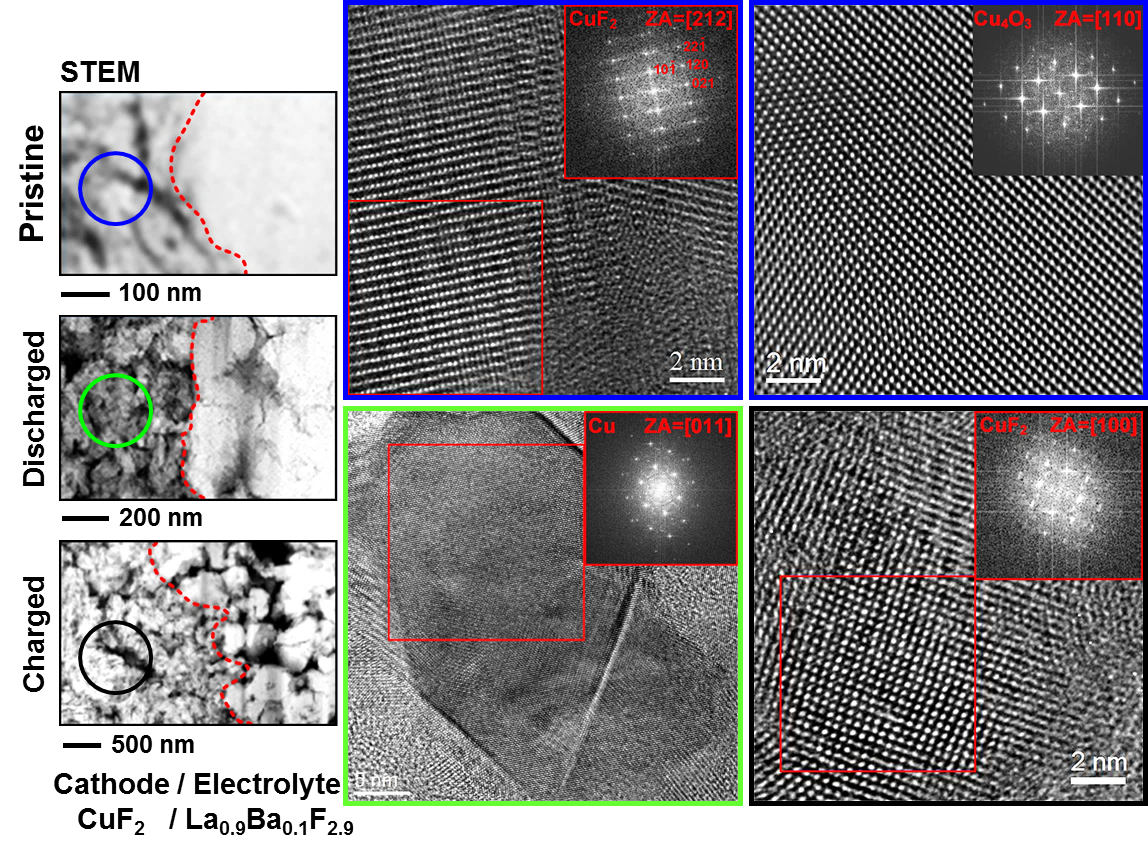
Figure 2: HRTEM images and corresponding FFTs of cathode.
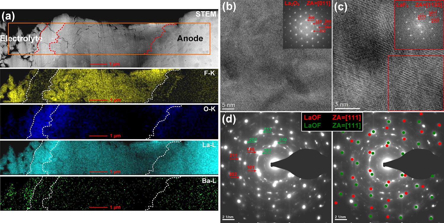
Figure 3: (a) STEM-EDX map of the anode-electrolyte interface after discharging, (b, c) HRTEM images and corresponding FFTs from an intermediate layer formed at the anode-electrolyte interface after discharging, (d) SAED pattern taken from the intermediate layer formed at the anode-electrolyte interface after discharging.
Details have been published at
- Reversible CuF2 as cathode for secondary Fluoride Ion Batteries
D. Tho Thieu, M. H. Fawey; H. Bhatia, T. Diemant, V. S. K. Chakravadhanula, R. Jürgen Behm, C. Kübel, M. Fichtner Advanced Functional Materials 2017 27, 1701051, DOI:10.1002/adfm.201701051.
2 In situ TEM studies of fluoride ion batteries
In addition to the ex situ TEM analysis shown above, we are developing new preparation and analysis approaches to follow the structural changes in the micron-sized all-solid-state batteries and half-cells in situ using TEM techniques. The FIB has been used to cut a thin cross-section from an all-solid-state battery that is then mounted and contacted to the electrical contacts of a MEMS device (Figure 2.4). The MEMS device, carrying the micron-sized battery, is transferred under (close to) inert conditions to an Aduro sample holder in the TEM for in situ cycling (Figure 2.5).
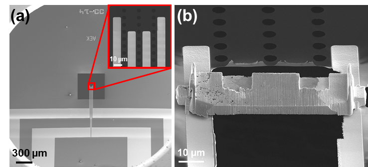
Figure 2.4: SEM images of (a) blank MEMS device (Protochips E-AEK11) with a 50 µm wide separation between Pt electrical contacts, and (b) an actual micron-sized battery mounted on a MEMS device.
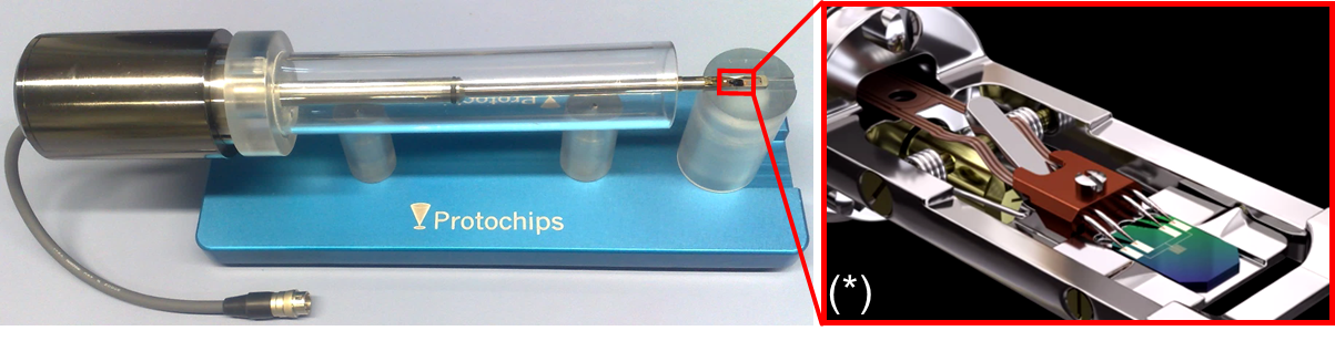
Figure 2.5: An Aduro sample holder from Protochips company for in situ TEM electrical biasing, heating up to 1200 °C and electrothermal analysis. (*) http://www.protochips.com/products/fusion/.
The batteries that have been studied by in situ TEM are all-solid-state fluoride ion batteries. We have performed a first successful in situ cycling experiments for two systems of all-solid-state fluoride ion batteries, where reasonable I-V charging-discharging curves have been obtained. Moreover, the structural and compositional changes during cycling were imaged. The two systems that are cycled in situ TEM are:
- A half-cell consisting of Bi/La0.9Ba0.1F2.9/C as electrode and La0.9Ba0.1F2.9 as solid electrolyte. The half-cell was cycled by applying a sweep voltage between 0 V and 3 V. The formation of BiF3 and BiO0.1F2.8 at the cathode after charging was confirmed by HRTEM and SAED, which were absent in the as-prepared state (Figure 2.6).
- A full cell consisting of Cu/C as cathode composite, Mg/MgF2/La0.9Ba0.1F2.9/C as anode composite, and La0.9Ba0.1F2.9 as solid electrolyte. The full cell battery was cycled by applying a sweep voltage between 0 V and 3.5 V. The formation of CuF2 after charging was confirmed from the HRTEM images, which was not present in the as-prepared state (Figure 2.7).
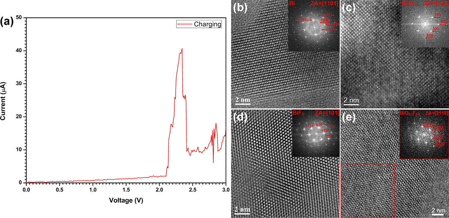
Figure 2.6: (a) Cyclic voltammetry curve of Bi/La0.9Ba0.1F2.9 half-cell obtained during the 1st charge, (b, c) HRTEM images and corresponding FFTs of the electrode before cycling, (d, e) HRTEM images and corresponding FFTs of the electrode after charging.
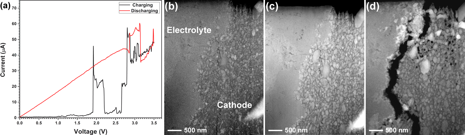
Figure 2.7: (a) Cyclic voltammetry curves of Cu/La0.9Ba0.1F2.9/MgF2 full cell, (b-d) morphological changes of the cathode-electrolyte interface before cycling, after 1st cycle and after 2nd charging; showing Cu coarsening, void formation and finally delamination at the cathode-electrolyte interface.
Details have been published at
- In situ TEM Studies of Micron-sized All-solid-state Fluoride Ion Batteries: Preparation, Prospects, and Challenges
Mohammed Hammad Fawey, Venkata Sai Kiran Chakravadhanula, Munnangi Anji Reddy, Carine Rongeat, Torsten Scherer, Horst Hahn, Maximilian Fichtner, and Christian Kübel
Microscopy Research and Technique 2016, 79, 615–624, DOI:10.1002/jemt.22675.